Stair running water lights: how the step-by-step effect works and how to install it
A stair running water light lights the treads one after another as you climb, holds them while you are on the flight, and switches them off behind you once you have left it. A sensor at each end tells the controller which way you are going. Half of the result is the hardware; the other half is what was buried in the wall before the plaster went on.
Key takeaways
- One controller channel per step plus two spare: a 14-step flight fits a 16-channel unit, a 20-step flight does not.
- Supply wattage = steps × lit width × W/m, plus 20 percent: 14 steps of 0.9 m at 8 W/m needs 150 W.
- Main-line wiring, one cable per step, must go in before plastering; a single addressable bus is the only retrofit that keeps the running effect.
- Mount both sensors 30–50 cm above the tread on the first and last step, aimed across the flight, never on the landing.
- Start at 0.3–0.5 s per step, 20–40 s dwell, 3000 K, and a low night-level brightness.
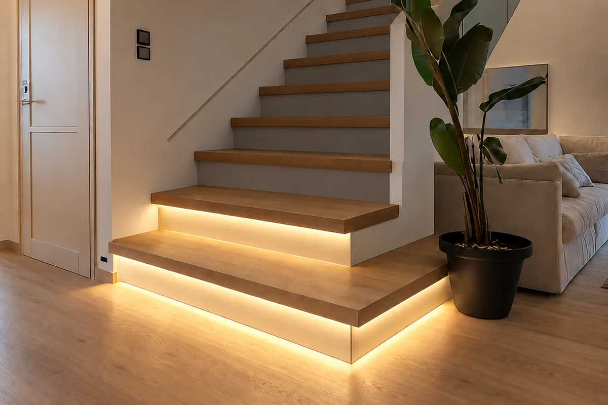
What happens when you step on the stairs
The sequence is short, and every setting on the controller maps onto one part of it.
- Trigger. You walk past the sensor at the bottom of the flight. It reports to the controller, and because it was the bottom sensor rather than the top one, the controller now knows the direction of travel.
- Run up. The controller switches on the first step, waits a set interval, switches on the second, and so on to the top. On most units the interval is adjustable between about a tenth of a second and a full second per step.
- Hold. The whole flight stays lit for the dwell time, counted from the last trigger the controller saw. Passing the sensor at the top counts as a trigger and resets the clock.
- Run off. When the dwell time expires the steps switch off in sequence, normally in the direction you walked, so the light appears to follow you out.
Coming down reverses the order. A daylight sensor, where one is fitted, holds the whole system off while the room is bright enough not to need it.
What each part of the kit does
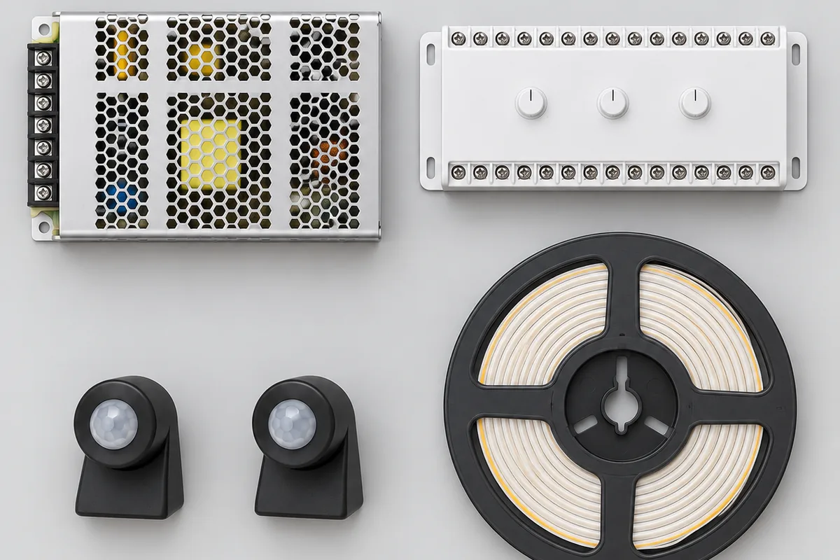
Main controller
The controller is the only intelligent part. It takes the two sensor inputs, drives the strip on every step, and holds the settings: order, speed, brightness, dwell time and the daylight threshold. Stair controllers are sold by channel count — 16, 20, 24 and 32 outputs are common — and you need at least one channel per step, including the landing if it is to be lit. A 14-step flight on a 16-channel unit leaves two spare. A 20-step flight on the same unit cannot be done at all. Buy for the flight you have plus a couple of spare channels, not for the nearest size down.
Sensors
Two of them, one at each end of the flight, on the side wall roughly 30 to 50 cm above the tread. Passive infrared (PIR) sensors respond to body heat moving across their field of view and need a clear line of sight. Microwave radar sensors respond to movement, and can see through a thin cover or even a light partition, which lets them hide behind a panel but also lets them trigger from the far side of a wall. Both work; the placement rules differ.
LED strip
Nearly every current kit uses 24 V COB strip: the LED chips sit under a continuous phosphor layer, so the light under the nosing is an unbroken line rather than a row of dots, even without a diffuser. 24 V rather than 12 V halves the current for the same wattage, which means thinner cable and less voltage drop on the long run to the top step, so the top tread is no duller than the bottom one. It is cut to the width of each tread at the marked cut points and fixed under the nosing or along the riser, in a routed channel or an aluminium profile.
Power supply
A constant-voltage supply converts the mains to 24 V DC for the controller and the strip. It is sized from the total strip length, and it is the one component people routinely undersize.
How to size the power supply
- Add up the lit length. Number of steps times the lit width of each tread. Fourteen steps at 0.9 m is 12.6 m.
- Multiply by the strip's rated watts per metre. At 8 W/m that is about 101 W.
- Add 20 percent. A supply run at its full rating runs hot, ages fast, and has no margin for the moment when every step is on at once. 101 W becomes 121 W.
- Buy the next standard size up. Here that is 150 W. A 100 W unit is not enough, even though the number on the box is close.
The supply should also have short-circuit protection. A stair install involves more cut ends and more joints than almost any other strip install — one segment per step means a connection at every tread — and what happens when one of those joints bridges is decided by the supply, not the strip. The bench test that tells you whether yours will shut down or cook the joint is in the stair placement guide. If the top step still looks duller than the bottom one after all that, the cause is cable length, and the fix is in sizing the supply and fixing a dim far end.
Mount the supply and the controller together somewhere with access: a cupboard under the stairs, a service hatch, the back of a hall cabinet. Never seal them inside the stair void. The supply is the component most likely to be replaced during the life of the installation.
Two ways to wire it: one cable per step, or a single bus
This choice decides whether the system can be retrofitted at all, so make it before anything else is bought.
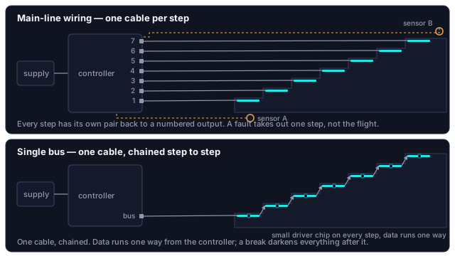
Main-line wiring
Every step has its own pair of wires running back to a numbered output on the controller. The controller produces the sequence by switching those outputs in turn, and the strip on each step is ordinary single-colour COB with no electronics of its own. It is the more fault-tolerant arrangement — a failed strip or a damaged cable takes out one step, not the flight — and it is what nearly all dedicated stair controllers expect. The cost is the cable bundle: fourteen steps means fourteen cables converging on one point, and they have to be in the wall before it is closed.
Single-bus wiring
One cable runs from the controller to the first step and then step to step up the flight. Each step's strip carries a small driver chip that gives it an address, and the controller sends the whole sequence down the one line. Far less cable, and the only scheme that can be added to a finished staircase without opening the wall. The trade-off is that the chain has a direction — data enters at the controller end and cannot be reversed afterwards — and a break at one step darkens everything after it.
| Main-line | Single bus | |
|---|---|---|
| Cable to the steps | One pair per step, all back to the controller | One cable, chained step to step |
| Strip on each step | Plain single-colour COB, no electronics | Addressable strip, a driver chip per segment |
| One fault takes out | That step only | That step and every step after it |
| Direction of the run | Set on the controller | Fixed at the controller end |
| Adding to a finished staircase | Not without opening the wall | Yes, surface-run in a slim profile |
| Colour | Three channels per step | No channel penalty |
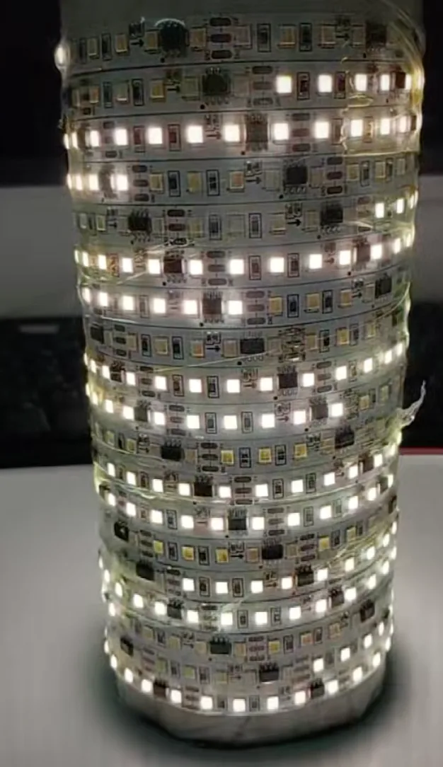
Why a plain RGB strip cannot do this on its own. All the LEDs on an ordinary RGB strip share three connections, so whatever the controller sends arrives everywhere at once. The strip is physically unable to light one step and leave the next one dark. Per-step control needs either a separate channel for every step or addressable segments with their own driver chips. No app setting changes that.
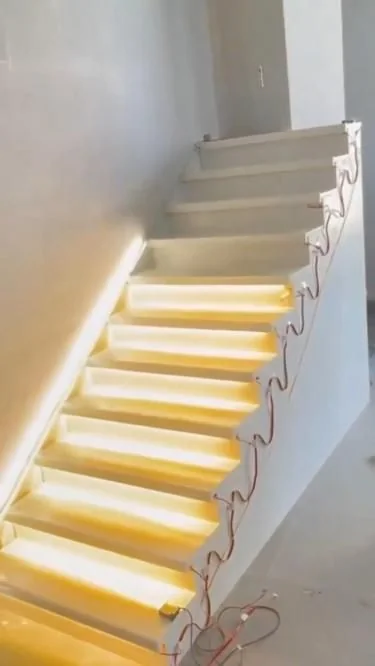
What has to be in the wall before the plaster goes on
Almost every stair-light project that fails does so here, at first fix, months before a light is bought. In order:
- A mains outlet where the controller will live. Top or bottom of the flight, inside a cupboard under the stairs, a service hatch or a cabinet that can be opened. The supply and controller sit next to it, and the low-voltage side starts from there.
- Conduit to every step. For main-line wiring, one run from the controller position to each step. For a single bus, one run to the first step and short links between steps. Use 16 or 20 mm conduit with a draw string, so the cable is pulled through after decorating rather than plastered in. This is the single item that cannot be added later.
- Sensor boxes at both ends. A small back box on the side wall at the first and at the last step, 30 to 50 cm above the tread, each with a conduit back to the controller. Face them across the flight rather than along it, and away from any doorway.
- The light channel. A groove 10 to 15 mm deep under each nosing, or a recess for an aluminium profile with a milky diffuser. Deep enough to hide the strip from someone looking up the stairs, shallow enough not to weaken the tread at the edge that takes the most load. Stone and tile treads are cut before they are laid, not after.
- Labels. Number every cable at the controller end as it goes in. Fourteen identical grey cables are effortless to label at first fix and impossible to identify afterwards.
If you are reading this with the walls already finished, skip to the retrofit options. Nothing in this list can be done without opening them again.
Placing the sensors so they see the stairs and nothing else
The most common complaint about a finished install — the whole flight lighting up because someone crossed the hall — is a coverage problem, not a fault. A sensor mounted at the top step with a wide detection cone sees the landing as well as the step, because the cone does not stop at the edge of the stairs.
- Mount at the first and the last step, not on the landing beyond them.
- Keep the height between 30 and 50 cm above the tread. Higher, and the cone reaches across the room; lower, and a bag or a pet triggers it.
- Aim across the flight rather than along it. A PIR sensor responds to a body crossing its field of view, and under-triggers when someone walks straight at it.
- Keep radar sensors for enclosed stairwells. They see through a thin partition, which is a feature behind a decorative panel and a nuisance next to a hallway.
- Keep PIR sensors away from radiators and heating vents, which they read as movement.
The detailed diagnosis, including masking part of a lens and moving a sensor lower down the flight, is in the stair placement guide.
Settings that make it feel natural
| Setting | Start here | Why |
|---|---|---|
| Step interval | 0.3 to 0.5 s per step | Matches walking pace, so the light stays a step or two ahead of your foot. Faster, and the flight simply switches on. Slower, and you outrun it, which is worse than no light |
| Dwell time | 20 to 40 s from the last trigger | Set for the slowest person who uses the stairs, carrying something, not for the fastest on a test run |
| Brightness | Low, night level | The job is to mark edges, not to light the room. Many controllers add a faint standby level on the first and last step so the flight can be found in the dark |
| Colour temperature | 3000 K | Warm white for homes; it flatters timber treads. 4000 K suits a white minimalist interior or a working space. Cool 6000 K at night reads as glare and delays your eyes readjusting to the dark |
| Daylight threshold | As low as it goes while still switching on at dusk | Keep the photocell out of the strip's own light, or the system switches itself off the moment the first step lights |
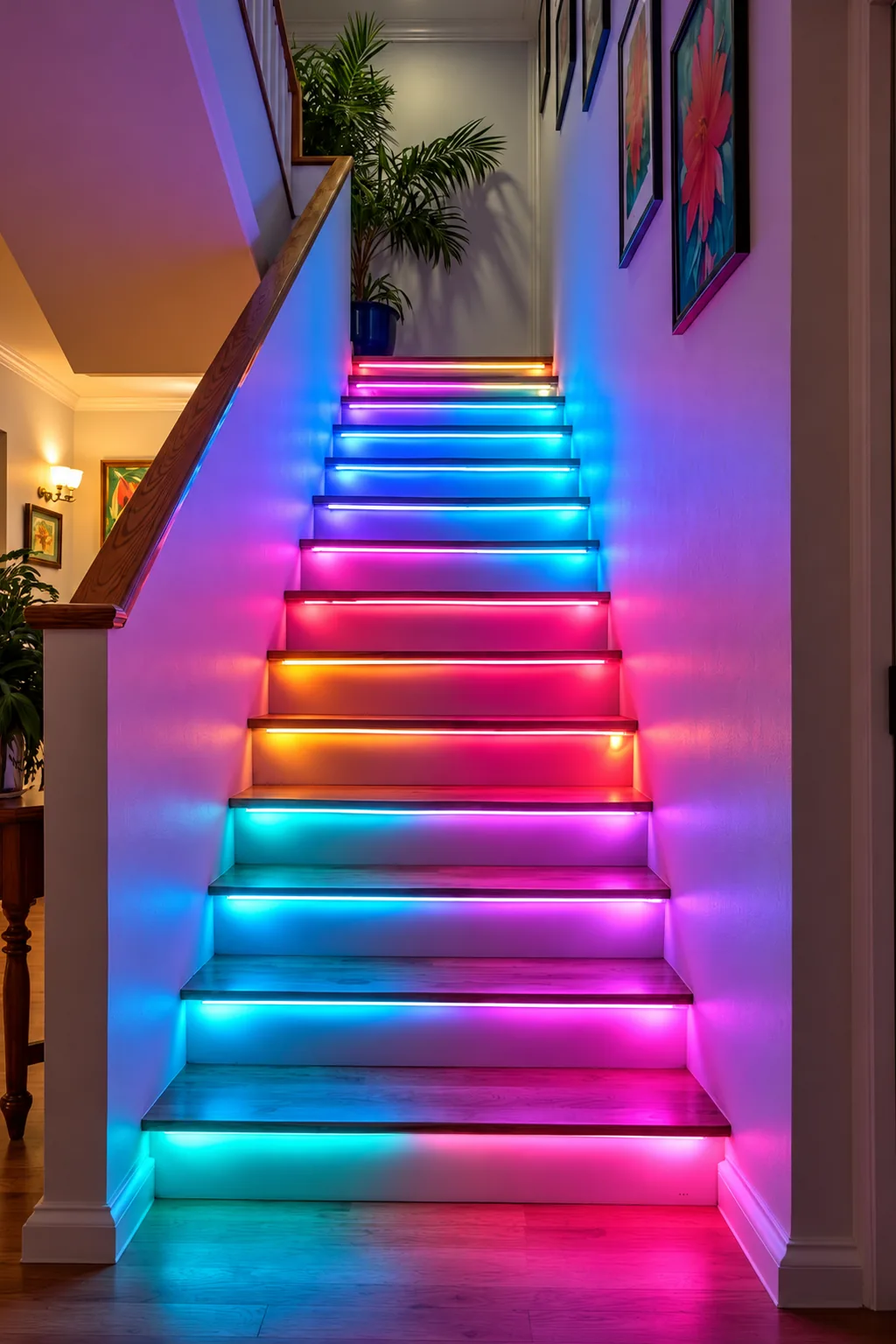
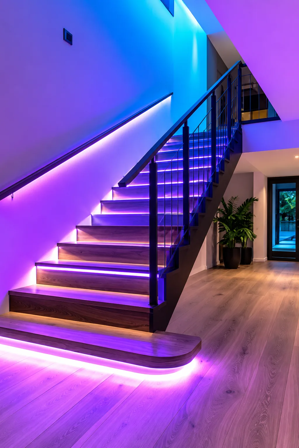
The two finished installs below sit at opposite ends of the taste range: per-step colour on a family staircase, and a single violet wash under the treads and along the skirting of an open-plan hall. The controller logic is identical. What differs is the strip, and how many channels the controller spends on each step.
If you want colour
Colour costs channels. RGB COB strip with an RGB stair controller uses three channels per step, so the channel count triples and a 32-channel unit covers ten steps. An addressable single bus handles colour natively with no channel penalty. Most people who install colour end up leaving it on warm white.
When nothing was pre-wired: the retrofit options
| Option | Wiring | Running effect | What shows | Upkeep |
|---|---|---|---|---|
| Single-bus addressable kit | One cable, surface-run in a slim profile along the stringer or under the skirting | Yes, true step by step | The profile; choose its colour against the wall or the stringer, not the strip | None |
| Wireless sensor lights, one per step | None; magnetic mounts, each with its own PIR sensor | No; each lights itself when it sees you | Fourteen small units | Fourteen batteries charged in rotation |
| One strip along the wall on a single sensor | One cable, one connection | No; the flight lights at once | One continuous line at skirting height | None |
The first option is the only way to get the true step-by-step effect on a finished staircase. The third gives the effect up and is often still the right call: on a straight flight where safety was the goal, it marks every step edge, and nothing about it needs the wall opened.
On our own stair controllers
The stair controllers we design are the app-connected kind. They pair in Lotus Lantern, and the step interval, the dwell time, the brightness and the standby level on the first and last step are all set in the app rather than on dials. In practice that means the settings get adjusted from the landing after dark, when the problem is visible, instead of at the cupboard where the controller lives with a torch in one hand. The always-on mode described in the placement guide is the same setting: it holds every step at the standby level instead of running the sequence, for a flight the sensors cannot cover well.
Pairing follows the same steps as any of our Bluetooth lights, shown in first-time pairing; if the box does not name the app, the mapping for every category does. Dial-adjusted units have no app at all and do not need one.
When the finished flight misbehaves
| What you see | Likely cause | What to do |
|---|---|---|
| The whole flight comes on at once | Interval at its shortest, or the controller in an all-on mode | Lengthen the interval until the run is visible, then shorten it to walking pace |
| It runs the wrong way | Sensors on the wrong inputs, or steps wired to the outputs in reverse | Swap the two sensor leads first: two wires rather than fourteen |
| One step stays dark, the rest are fine | Main-line: that step's cable, connector or strip | Check that step only; nothing else is affected |
| One step dark and everything above it too | Single bus: a break in the chain at that step | Remake the joint or replace that step's segment |
| Comes on in daylight, or never at all | Daylight threshold, or the photocell's position | Move the photocell out of the strip's light; one in a dark corner thinks it is always night |
| Lights when someone crosses the hall | Sensor cone covering the landing | Lower the sensor, aim it across the flight, or mask part of the lens |
If the walls are still open, run conduit to every step, box both sensors and label every cable at the controller end; that is the one moment when the advice is cheap. If they are finished, choose between the single-bus kit and the one-strip fallback. Either way, size the supply with 20 percent headroom before anything is ordered. Questions about a specific stair controller of ours? Contact us.