Y16: addressable pixels, up to a thousand per controller
TV backlights that follow the picture, corner lamps that scroll a gradient up a wall and firework lights whose tails fall in sequence all need an effect that moves, and on our controllers they are built on Y16. The platform drives strip and string in which every emitter holds its own colour value, and it keeps up to a thousand of them in step from a single small chip.
Key takeaways
- At 800 kbit/s one pixel takes 30 µs, so 1000 pixels take 30 ms per frame: about 30 frames per second, the floor for smooth motion.
- Two outputs of 500 pixels refresh twice as fast as one output of 1000. Split TV backlights and twin-column lamps across both.
- Wrong colour on every pixel is wire order; a dark tail or a pausing chase is pixel count. Both are settable in the app.
- Only the lead from controller to first pixel is length-critical; every pixel regenerates the signal for the next. Keep that lead short.
- A far end that goes warm and then dark is voltage drop reaching the drivers' minimum supply. Inject power at the tail.
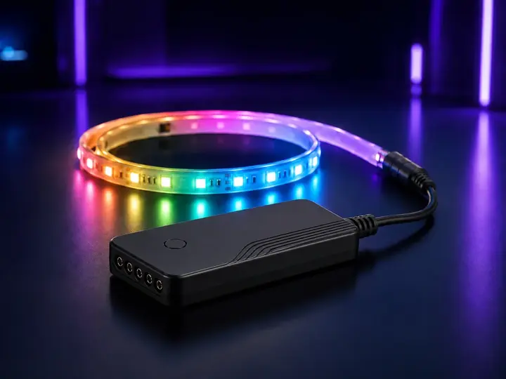
Addressable control: one data line, one driver per pixel
On a fixed-colour strip the controller drives three colour rails and every emitter shows the same mix. On an addressable strip each emitter, or each small group, sits behind its own driver IC with a fixed position in a chain. The controller sends one serial stream down a single data line: the first driver latches the first 24 bits it receives — eight each for green, red and blue, in the order the WS2812 family expects — regenerates the remainder and passes it on. When the stream ends, every driver holds its own value, and a pause of at least 50 µs on the line commits the frame to the LEDs. A new stream changes the picture; a stream sent often enough makes the picture move. The pixel IC also sets its own dimming frequency — not less than 400 Hz on early WS2812B parts, 2 kHz on current revisions — so banding on camera is a property of the strip specified, not of the controller.
That single data wire is why addressable products are sold as RGBIC and why they need a controller designed for the job. Y16 is that controller.
The numbers we stand behind
| Item | Y16 |
|---|---|
| Design | Single chip, SOP16 package — large-pitch pins, easy to place and easy to rework |
| Pixels per controller | Up to 1000, driven stably from the one chip |
| Outputs | Drives two strips, or one long strip, without an external buffer driver |
| Dynamic modes | More than two hundred |
| Music modes | Eight — two energy, two rhythm, two spectrum, two rolling |
| Configuration | Pixel count and wire order are configurable; strip or string |
| Control | Bluetooth app, 2.4 GHz or infrared remote, on-board buttons |
| App | Magic Lantern |
Why a thousand pixels is the ceiling
The figure follows from the data line. The common single-wire pixel protocol runs at 800 kbit/s, 1.25 µs per bit, and each RGB pixel needs 24 bits: 30 µs per pixel. A thousand pixels are therefore 24,000 bits and 30 ms per frame, plus the reset gap, which caps a thousand-pixel run at about 33 frames per second. The WS2812B datasheet states the same limit from the other side: at a 30 fps refresh rate the cascade is not to exceed 1024 pixels. Thirty frames per second is the rate at which a chase reads as motion rather than as steps.
Beyond that point the frame rate falls in proportion. Two thousand pixels on one output take 60 ms per frame, about 16 fps, and a chase that was fluid becomes visibly stepped. RGBW pixels such as SK6812 carry 32 bits each, so the same 30 ms budget holds 750 of them. The ceiling is the length at which one data line still animates smoothly; a project that needs more pixels needs more outputs or more controllers, not a longer run.
| Criterion | One output, 1000 pixels | Two outputs, 500 + 500 |
|---|---|---|
| Frame rate | About 33 fps at the ceiling | About 66 fps per output; headroom for fast chases |
| Wiring | One data lead; power injection needed along the run | Two data leads from one board; each half fed from its own end |
| Uniformity of light | Tail pixels furthest from both supply and data source | Each run half as long; half the voltage drop per run |
| Layout | One continuous line or loop | Symmetric pairs: left-and-top with right-and-bottom, twin columns |
| Timing | Continuous | Both outputs driven by one chip and one frame, so the halves stay in step |
Two outputs without a buffer
The data signal is a fast logic waveform. A pixel reads a level above 0.7 × its supply as high — 3.5 V on a 5 V strip — and the lead between the controller and the first pixel adds capacitance that rounds the edges of that waveform; past a certain length the first pixel misreads bits and the whole chain shows corrupted data. The conventional remedy is a buffer IC on the output. Y16 drives two strips, or one long strip, directly from the chip, which removes a component, a solder joint and a failure point, and is one reason the platform fits inside a corner-lamp base or a firework-light hub without its own box.
Only the first lead is length-critical. Every pixel IC reshapes the waveform it received before passing it on, so the WS2812B datasheet allows more than 5 m between any two adjacent pixels without additional circuitry, and distortion does not accumulate along the chain. Independent tests on WS2812B and SK6812 strip put a 26 AWG lead from a buffered output with a series resistor at 5 m without errors; sporadic glitches appear at 10 m on older parts and frequent errors at 15 m, while 18 AWG conductors run 20 m cleanly. In a fixture the rule is a short, direct lead from the controller to the first pixel, with distance covered by the strip itself.
Two outputs also serve layout. A TV backlight is two runs — left-and-top and right-and-bottom — meeting at the centre of the top edge. A corner lamp is often two columns. Feeding both from one controller, in step, without a second board is what makes those products simple to build.
Configurable pixel count and wire order
Two settings decide whether a controller works as delivered or generates a support call, and Y16 exposes both.
Pixel count tells the controller the length of the run. Set too low, the end of the strip stays dark; set too high, the effects run off the end into pixels that do not exist, so a chase appears to pause before restarting. It is set for the product at build time and adjustable in the app on products that expose it.
Wire order is the sequence in which a pixel expects its colour bytes. The WS2812 family expects green, then red, then blue; other ICs expect red first, a few blue first, and RGBW pixels add a fourth byte. A wrong order shifts every colour identically: red comes out green, green comes out blue. Because the order is a setting rather than a firmware constant, a product can be built on whichever pixel strip is available, and a customer who has replaced a strip can correct it in the app. Colours coming out wrong is the guide for that fix.
Modes, and the eight music modes
Two hundred dynamic modes is a large figure because a mode on an addressable run is not a colour but a pattern over time and position: gradient direction, chase width, fade rate, whether segments move together or in opposition. The count reflects those combinations. What matters in a fixture is that the modes it ships with are present and that transitions stay smooth at the run length installed.
The eight music modes come in four pairs, each responding to a different property of the sound picked up by the controller's own microphone:
- Energy — overall loudness drives brightness or lit length.
- Rhythm — beats trigger discrete events, a flash or a colour change.
- Spectrum — low, middle and high frequencies map to different colours or positions along the run.
- Rolling — the sound drives a pattern that travels along the run rather than flashing in place.
Because the microphone is on the controller, these modes continue after the phone is put away — the distinction music sync: three modes explains.
Remotes without a receiver window
Y16 takes a 2.4 GHz radio remote as well as infrared. Infrared needs a receiver behind a window in the enclosure and a clear line of sight to it, which a controller behind a television or inside a lamp base rarely has. The 2.4 GHz path needs no window and no receiver module, so the controller can be concealed entirely and the enclosure sealed; its cost is comparable to an infrared receiver and below a 433 MHz one. The remote is built on a dedicated 2.4 GHz transmitter or a Bluetooth LE SoC, with short-press, long-press and a sleep state, and its faceplate and board can be standard or custom.
| Criterion | Infrared | 2.4 GHz |
|---|---|---|
| Line of sight | Required; 940 nm emitter on a 38 kHz carrier, receivers rated about 8 m | Not required; 12.5 cm wavelength passes furniture and lamp housings |
| Enclosure | Window facing the room | Closed and sealable; antenna inside |
| Fixture placement | Receiver must face the seating position | Behind the TV, inside the base, out of sight |
| Cost position | Lowest | Comparable to an infrared receiver; below 433 MHz |
What a product on Y16 can be customised to do
For a light being specified: the mode set, the infrared or 2.4 GHz remote code values, the on-board button functions, the power-on animation, the music modes, the pixel count and wire order, and strip-versus-string output are all set when a product is built. On the hardware side the board outline, remote interface, button count and external microphone circuit are variables; the app can be white-labelled. The platform's limits — a thousand pixels, two outputs — do not move.
Mistakes we see most often
Only the first pixel lights, or the first few flicker
Almost always the data line: a long unshielded lead between controller and strip, a poor joint at the first pixel, or a first driver that has failed and no longer passes data. Substitute a short lead; if the strip runs close to the controller and fails far from it, the lead is the fault.
The pattern stops short of the end, or seems to pause
Pixel count does not match the run. Compare the setting with the number of pixels connected, allowing for a cut-and-rejoined strip having fewer than the reel it came from.
Colours are wrong on every pixel, consistently
Wire order. If red comes out green everywhere, the strip is not faulty — change the order setting.
The far end is dim and reddish
Voltage drop on the power rails. Addressable strip shows it as the far pixels going warm before they go dim, and it is more sensitive than fixed-colour strip because each driver IC needs a minimum supply to operate at all — a 5 V WS2812B is specified from 4.5 V. Inject power at the far end; strip length and power has the numbers.
Common questions
Can Y16 drive an ordinary RGB strip?
No. An ordinary RGB strip has colour rails and no data line; it needs the Y96 platform. The two are different kinds of strip, not different lengths of the same one.
Can I join two addressable strips to make a longer run?
Yes, up to the thousand-pixel ceiling on one output, provided both strips use the same pixel chip. Mixing pixel types on one data line does not work, because they may expect different timing or a different wire order.
Which app runs it?
Magic Lantern. Full mapping here.
Contact us if you are building a light on this platform and need a detail that is not here.
Sources: WS2812B datasheet (timing, reset, GRB order, 30 fps / 1024 pixels, 5 m pixel-to-pixel); WS2812B-2020 datasheet (2 kHz refresh); SK6812 RGBW datasheet (32-bit pixels); QuinLED, maximum data-wire length tests; Adafruit 940 nm / 38 kHz IR transceiver; Vishay TSSP98038, 8 m range.