Chaining LED light screen panels into one display
Three panels on the wall, one picture across them — and the right-hand third of the image is showing on the left. The link cables are fine. What is wrong is the description of that wiring in the app, and a working assembly showing a broken picture is the more common of the two ways this job goes wrong.
Key takeaways
- Data runs from panel to panel through the link cable. Current does not: every panel takes its own 5 V feed from the supply.
- Whites turning pink and the last panel dimming on bright content are voltage sag, not a colour setting.
- Test with full white at full brightness on every panel before anything is mounted.
- Set each panel's order and orientation in the app. A scrambled picture is a mapping error, not a fault.
- Two chains of three refresh faster than one chain of six. Use separate controller outputs.
Feed power into every panel, not only the first
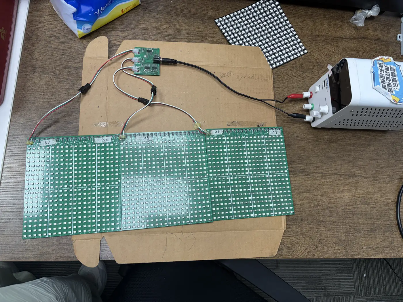
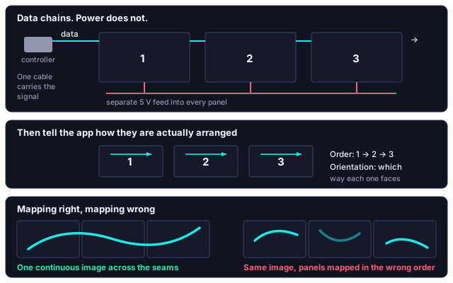
Data chains from panel to panel. Power must be fed into every panel separately.
The link cable between panels carries the signal onward. It cannot carry the current for three panels through the first panel's traces. Each panel takes its own feed from the supply.
The reason is the size of the current. Take the full-white figure per pixel from the panel's spec sheet — for a common 5 V addressable pixel it is around 60 mA — and multiply by the pixel count. A 600-pixel panel, 20 across and 30 down, comes to some 36 A at full white; three of them pass 100 A. None of that belongs in the thin copper of a panel's traces or a three-wire link cable.
At 5 V there is also no margin. Half a volt lost along a cable is a tenth of the supply, and the blue and green emitters inside each pixel need about 3 V to light where red needs about 2 V. So a rail that is sagging turns white pink before it turns anything dim.
This applies from two panels upward. On our own test bench every panel has its own 5 V feed marked at the injection point, and that is done before anything is run.
Under-fed power looks like a fault:
| What you see | What it is | Do this |
|---|---|---|
| Whites go warm or pink the further you get from the feed | Voltage sag along the chain, not colour calibration | Add a feed at the panel where the drift starts |
| Each panel dimmer than the one before it, at the same setting | Current for later panels passing through earlier ones | Feed every panel from the supply |
| A dark image is perfect; full white flickers, dims or resets | Supply too small for bright content — draw scales with what is lit | Size the supply for full white, not the demo effect |
| The far panels flicker or restart at random | Voltage at the end of the run below what the control chips need | Feed the far end; use shorter, thicker supply leads |
If any of those describe what you are seeing, add power before you change anything in the app. Sizing the supply from the pixel figures is the same job as for strip, and is set out in LED strip length and power.
Test with full white before anything goes on the wall
A photograph with dark areas might light a third of the panel. A plain white screen lights all of it, at full output, on all three colours. So test with full white at full brightness, across every panel at once. If the assembly is stable there, everything else is easier. Sizing a supply against a dark test image is how people end up with a screen that works for a week and then browns out during the one bright scene they actually wanted.
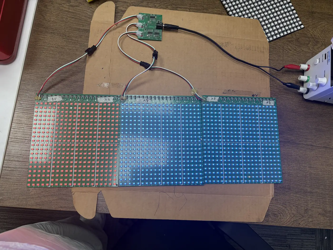
Fill each panel with a different solid colour before you go to white, as above. It does two jobs at once: it shows whether the addressing boundaries fall where the physical panel edges are, and it loads a whole panel at a time, so you can watch for sag panel by panel rather than all at once.
If a fill spills across a seam — part of the second panel showing the first panel's colour — the panel size or count in the app does not match the hardware, and no amount of power fixes that.
Telling the app how the panels are arranged
Once the wiring is sound, the second half of the job is describing the physical arrangement in the app. The controller sends one continuous stream of pixel data down the chain. It has no way of knowing where you physically put each panel, or which way round you mounted it. Two panels sat side by side and two panels stacked vertically receive exactly the same data — so you have to tell the app which arrangement is on the wall.
In the app you set, for each panel:
- Order — its position in the sequence, matching the order the data cable actually visits them.
- Orientation — which way that panel is facing, since a panel rotated or flipped during mounting receives its slice of the image the wrong way round.
Panels carry printed numbering along the edges for this: you read the arrangement off the hardware and enter the same thing in the app rather than working it out from first principles.
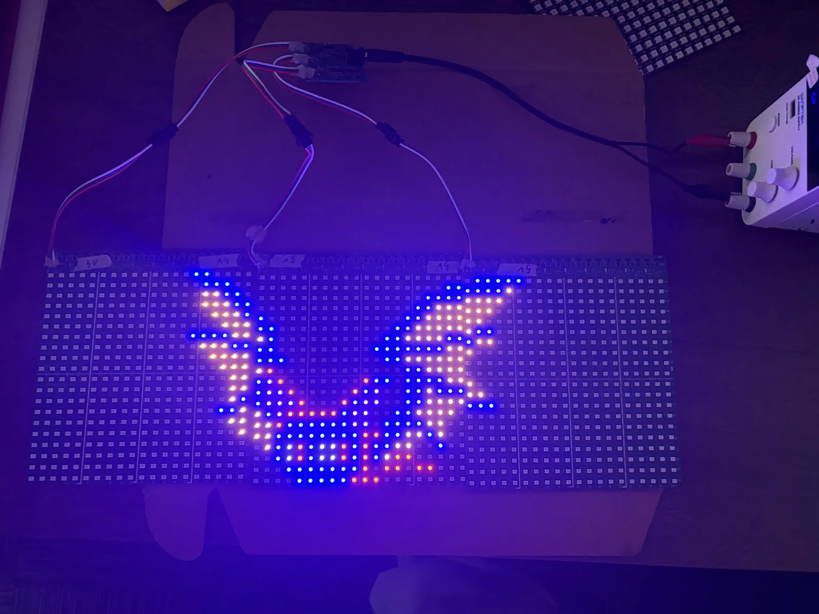
Reading a scrambled image
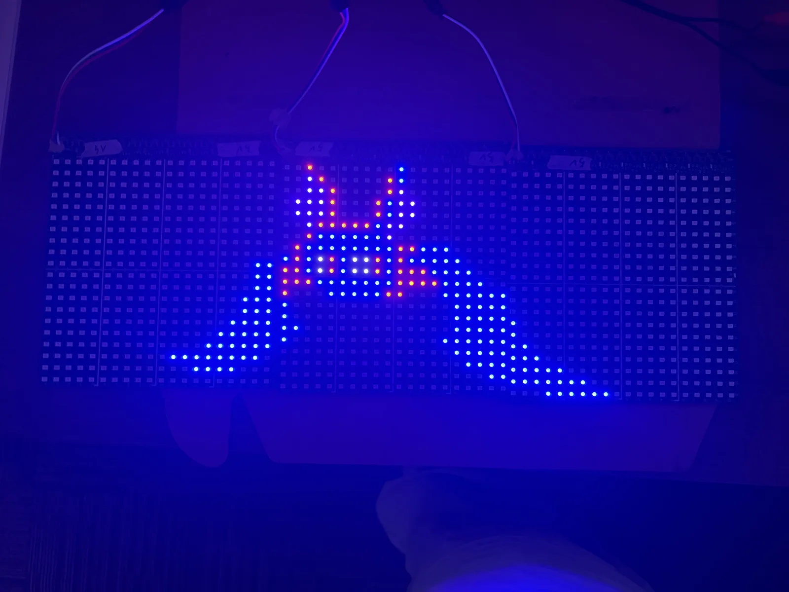
When the mapping is wrong, the failure is usually specific enough to point at the cause.
| What you see | Usually means |
|---|---|
| Image is complete but the panels are in the wrong places — right-hand chunk showing on the left | Panel order in the app does not match the order the data cable visits them |
| One panel's section is mirrored or upside down while the rest is correct | That panel's orientation setting does not match how it is physically mounted |
| Image is squashed into the first panel and the rest is dark | The app thinks the display is smaller than it is — panel count or total size is short |
| Image runs off the end and part of it never appears | The app thinks the display is bigger than it is |
| Every other row within a panel is reversed | Scan direction setting does not match how that panel is wired internally |
| First panel correct, everything after it dark | Data is not reaching the second panel — check the link cable and its direction |
Work these one at a time with a test image that is obviously asymmetric — text, or an arrow. A symmetrical pattern hides mirroring, which is exactly the fault you are trying to find. If the layout is right but the colours are wrong on every pixel, that is a different setting: see wrong colours and the Pixels setting.
One panel on its own, or all of them as one canvas
You are not obliged to treat the assembly as one canvas. The app can drive a single panel on its own, or the whole set as a combined display.
- Single-panel display suits small graphics and text that would be lost across a wide assembly, and it is the sensible mode while you are testing one panel or checking a suspect one.
- Combined display is what you want for one image across the whole width — a picture, a long scroll of text, an effect that travels the full span.
When planning content: an image spread across a combined display gets the resolution of the whole assembly, but text sized for one panel becomes small relative to the total width. Wide assemblies suit scrolling text better than a single static word. What the grid can show at all, and from how far away, is in what a pixel light screen can actually display.
Mounting so the seam disappears
Electrically the seam does not matter. Visually it is the thing people notice.
- Keep the pixel pitch continuous across the join. A gap wider than the spacing between LEDs inside a panel reads as a dark line through every image. Butt the panels as close as the housings allow.
- Align rows before fixing anything. A panel a few millimetres high or low makes a diagonal line look stepped. Run a straight edge along the top of the assembly.
- Support each panel independently. Do not let one panel hang off its neighbour, and do not let the link cable take any weight.
- Leave slack at every connector. Cables pulled taut between panels work their connectors loose over time, and an intermittent data link on panel two takes out everything after it.
How many panels can one controller drive?
Two separate limits apply, and the lower one wins.
The data limit is how many pixels the controller can address in total. Past that point extra panels either stay dark or repeat what an earlier panel is showing.
The refresh limit arrives sooner in practice. A single-wire pixel data line runs at about 800 kbit/s and each pixel takes 24 bits, so 1,000 pixels on one output take roughly 30 ms per frame — about 30 frames a second, the point where motion still reads as motion. Three 600-pixel panels on one output are 1,800 pixels and nearly 55 ms a frame, under 20 frames a second, and a scroll that was smooth on one panel starts to step. If motion is stuttering on a large assembly while static images look fine, you are past the comfortable limit for that output rather than at a fault. The arithmetic behind the ceiling is on the Y16 pixel controller page.
This is why our controllers provide several independent outputs rather than one long chain — the board in the bench photo above has three. Splitting the assembly across outputs divides the work and keeps the refresh rate up. If you have a choice between one chain of six and two chains of three, take the two chains.
For the specific limits of the controller you have, check its documentation or ask us — the numbers differ between models and we would rather give you the right one than a general figure.
The order to do the whole job in
- Lay the panels out flat in the arrangement you intend, before mounting anything.
- Chain the data cables in a deliberate order, and note that order.
- Feed power to every panel individually.
- Test with full white at full brightness, all panels lit, before you mount anything.
- Set the order and orientation in the app to match your layout, and check with an asymmetric test image.
- Only then mount it, aligning rows and leaving slack at the connectors.
Every problem on that list is easy to fix on a table and awkward to fix on a wall. If the assembly connects and shows colour but the panel effects are missing altogether, you have a general RGB app rather than the screen app — check which app controls your light before going any further.
Questions about a specific panel or controller of ours? Contact us.